


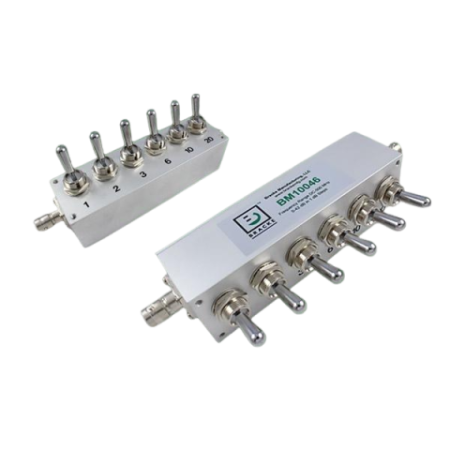

Manually adjustable RF attenuators – toggle control, up to 1 GHz: BM10046-BM10053 | Bracke Manufacturing

Bracke BM10046 to BM10053 toggle RF attenuators with BNC female connectors, 50 or 75 ohms, frequencies up to 1 GHz and attenuation ranges up to 102 dB.
The BM10046 to BM10053 models are manually adjustable coaxial RF attenuators featuring toggle control and BNC female connectors. The product family includes versions for both 50-ohm and 75-ohm signal paths.
Depending on the model, the maximum frequency is 500 MHz or 1 GHz. Attenuation can be adjusted in 0.5 or 1 dB steps. Available attenuation ranges are 0 to 42 dB, 0 to 82.5 dB or 0 to 102 dB.
Advantages
- Manual toggle control: Direct adjustment of defined attenuation values.
- 50- and 75-ohm versions: Selection according to the impedance of the coaxial signal path.
- Frequencies up to 1 GHz: Model versions with maximum frequencies of 500 MHz or 1 GHz.
- Attenuation ranges up to 102 dB: Selection according to the required adjustment range.
- Step sizes of 0.5 or 1 dB: Different resolutions for manual signal-level adjustment.
- BNC female connectors: Common coaxial interface across all listed models.
Key features
- Product type: Manually adjustable toggle RF attenuator
- Manufacturer: Bracke
- References: BM10046 to BM10053
- Impedance: 50 or 75 ohms, depending on the model
- Connector: BNC female
- Maximum frequency: 500 MHz or 1 GHz, depending on the model
- Attenuation range: 0 to 42 dB, 0 to 82.5 dB or 0 to 102 dB
- Step size: 0.5 or 1 dB
- Attenuation accuracy: Model-dependent, from ±1.0 to ±6.25 dB
- VSWR: Not specified in the provided information.
Typical applications
- Manual adjustment of defined attenuation values in coaxial RF signal paths
- Step-by-step variation of signal levels in measurement and test setups
- Comparative measurements requiring repeatable attenuation settings
- Laboratory and development setups using BNC interfaces
- Signal conditioning in 50- or 75-ohm measurement chains
Additional information
The appropriate model is selected according to the required system impedance, maximum frequency, attenuation range and step size. Models with 0.5 dB steps provide finer manual adjustment, while versions with 1 dB steps cover attenuation ranges up to 102 dB.
EMCO supports the technical selection of the appropriate toggle attenuator and its positioning within the complete RF measurement or test chain.
Model comparison – 50-ohm versions
| Reference | Impedance | Connector | Max. frequency | Attenuation range | Step size | Attenuation accuracy |
|---|---|---|---|---|---|---|
| BM10046 | 50 ohms | BNC female | 500 MHz | 0 to 42 dB | 1 dB | ±3.5 dB |
| BM10047 | 50 ohms | BNC female | 500 MHz | 0 to 82.5 dB | 0.5 dB | ±6.25 dB |
| BM10048 | 50 ohms | BNC female | 1 GHz | 0 to 42 dB | 1 dB | ±1.0 dB |
| BM10049 | 50 ohms | BNC female | 1 GHz | 0 to 82.5 dB | 0.5 dB | ±1.5 dB |
| BM10050 | 50 ohms | BNC female | 1 GHz | 0 to 102 dB | 1 dB | ±1.5 dB |
Model comparison – 75-ohm versions
| Reference | Impedance | Connector | Max. frequency | Attenuation range | Step size | Attenuation accuracy |
|---|---|---|---|---|---|---|
| BM10051 | 75 ohms | BNC female | 1 GHz | 0 to 42 dB | 1 dB | ±1.0 dB |
| BM10052 | 75 ohms | BNC female | 1 GHz | 0 to 82.5 dB | 0.5 dB | ±1.5 dB |
| BM10053 | 75 ohms | BNC female | 1 GHz | 0 to 102 dB | 1 dB | ±1.5 dB |

Related articles
 BRACKE Manufacturing now at EMCO: RF and Microwave Components