


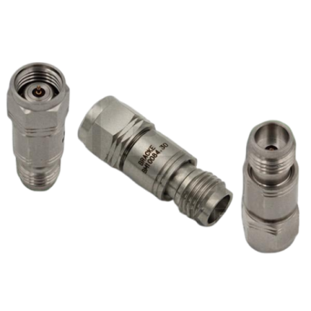

Coaxial millimeter-wave attenuators – 1.85 mm, up to 67 GHz: BM10084 Series | Bracke Manufacturing

BM10084 Series coaxial 50-ohm attenuators with 1.85 mm connectors, attenuation values from 3 to 30 dB and frequency ranges up to 67 GHz.
The Bracke Manufacturing BM10084 Series consists of coaxial attenuators with a 1.85 mm male-to-female configuration and a characteristic impedance of 50 ohms.
The series provides attenuation values of 3, 6, 10, 15, 20 and 30 dB. Depending on the model, the specified frequency range extends from DC to 65 GHz or from DC to 67 GHz.
Advantages
- Wide frequency range: Operation from DC to 65 GHz or up to 67 GHz, depending on the model.
- Six attenuation values: Choice of 3, 6, 10, 15, 20 or 30 dB.
- 50-ohm system impedance: Integration into corresponding coaxial RF and millimeter-wave signal paths.
- Male-to-female configuration: Direct insertion into coaxial connections using compatible interfaces.
- Extended temperature range: The 3 dB model is specified for operation from −55 to +125 °C.
- Metal body: Stainless steel or passivated stainless steel, depending on the model.
Key features
- Product type: Coaxial RF and millimeter-wave attenuator
- Connectors: 1.85 mm male to female according to the product descriptions
- Impedance: 50 ohms
- Attenuation values: 3, 6, 10, 15, 20 or 30 dB
- Maximum frequency range: DC to 67 GHz
- Maximum input power: 1 or 2 W, depending on the model
- Contacts: gold-plated
- Insulators: PTFE
- Body: stainless steel or passivated stainless steel, depending on the model
Typical applications
- Defined signal-level reduction in coaxial 50-ohm signal paths
- RF and millimeter-wave measurement setups up to 65 or 67 GHz
- Laboratory and test systems using compatible 1.85 mm interfaces
- Signal-level adjustment between coaxial RF or millimeter-wave components
- Characterisation and testing of broadband signal paths
Additional information
The BM10084.3 model is specified with a stainless-steel body, a 2 W input power rating and an operating temperature range extending to +125 °C. According to the drawings, the 6 to 30 dB models use passivated stainless-steel bodies and have a maximum input power rating of 1 W.
The product descriptions for all models specify a 1.85 mm male-to-female interface. However, the material tables for models BM10084.6 through BM10084.30 use the designation “1.8mm connectors”.
EMCO provides technical support for selecting the appropriate attenuation value and integrating these components into RF and millimeter-wave measurement, test and system solutions.
Model comparison
| Model | Attenuation | Frequency range | Maximum VSWR | Attenuation accuracy | Input power | Operating temperature | Length |
|---|---|---|---|---|---|---|---|
| BM10084.3 | 3 dB | DC to 67 GHz | 1.40:1 | ±1.3 dB | 2 W | −55 to +125 °C | 0.775 in |
| BM10084.6 | 6 dB | DC to 65 GHz | 1.65:1 | ±1.5 dB | 1 W | −55 to +100 °C | 0.880 in |
| BM10084.10 | 10 dB | DC to 65 GHz | 1.65:1 | ±1.75 dB | 1 W | −55 to +100 °C | 0.880 in |
| BM10084.15 | 15 dB | DC to 65 GHz | 1.65:1 | ±2.5 dB | 1 W | −55 to +100 °C | 0.890 in |
| BM10084.20 | 20 dB | DC to 65 GHz | 1.65:1 | ±2.5 dB | 1 W | −55 to +100 °C | 0.890 in |
| BM10084.30 | 30 dB | DC to 65 GHz | 1.65:1 | ±5.0 dB | 1 W | −55 to +100 °C | 0.880 in |

Related articles
 BRACKE Manufacturing now at EMCO: RF and Microwave Components