


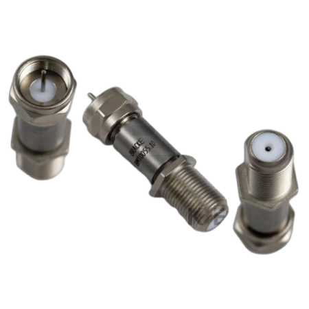

DC bias passing coaxial attenuator – 75 Ω, 0.5 to 2 GHz: BM10055 Series | Bracke Manufacturing

BM10055 Series 75-ohm DC bias passing coaxial attenuators for 0.5 to 2 GHz, with F male to F female connectors and 3, 6 or 10 dB attenuation.
The Bracke Manufacturing BM10055 Series consists of fixed coaxial attenuators with F male to F female connectors for 75-ohm RF systems. The models operate over a frequency range of 0.5 to 2 GHz and are available with fixed attenuation values of 3 dB, 6 dB or 10 dB.
The integrated DC bias passing capability allows RF signals and DC power to be transmitted through the same coaxial connection. The attenuators are therefore suitable for systems in which active components are powered through the RF line.
Advantages
- 75-ohm impedance for compatible coaxial, broadband and distribution networks
- 0.5 to 2 GHz frequency range
- DC bias passing up to 100 V and 2 A
- Choice of 3 dB, 6 dB and 10 dB fixed attenuation
- F male to F female connectors for direct inline integration
- Maximum VSWR of 1.45:1 at 2 GHz
- Compact coaxial construction with a nickel-plated brass body
Key features
- Impedance: 75 Ω
- Frequency range: 0.5 to 2 GHz
- Attenuation values: 3 dB, 6 dB or 10 dB
- Attenuation accuracy: ±1.5 dB
- Maximum VSWR: 1.45:1 at 2 GHz
- Maximum RF input power: 2 W
- Maximum DC voltage: 100 V
- Maximum DC current: 2 A
- Connectors: F male to F female
- Body material: nickel-plated brass
- Contact finish: nickel plated
- Insulator: PTFE
- Compliance: RoHS compliant
Typical applications
- Controlled level adjustment in 75-ohm RF signal paths
- Attenuation in coaxial broadband and signal distribution systems
- Protection of sensitive RF inputs against excessive signal levels
- Improved matching between coaxial system components
- Test and measurement setups requiring simultaneous RF and DC bias transmission
- Inline integration in systems using F connectors
Additional information
The attenuators have an overall length of approximately 41.7 mm, or 1.640 inches. 7/16-inch hexagonal surfaces are provided for installation.
The appropriate model should be selected according to the required attenuation value and operating temperature range. EMCO provides technical support for product selection and integration into RF, test and measurement systems.
| Model | Attenuation | Frequency range | Impedance | Maximum VSWR | Operating temperature |
|---|---|---|---|---|---|
| BM10055.3 | 3 dB | 0.5 to 2 GHz | 75 Ω | 1.45:1 at 2 GHz | −65 to +125 °C |
| BM10055.6 | 6 dB | 0.5 to 2 GHz | 75 Ω | 1.45:1 at 2 GHz | −55 to +125 °C |
| BM10055.10 | 10 dB | 0.5 to 2 GHz | 75 Ω | 1.45:1 at 2 GHz | −55 to +125 °C |

Related articles
 BRACKE Manufacturing now at EMCO: RF and Microwave Components