



Continuously variable RF attenuators – SMA, 1 to 18 GHz: BM Series | Bracke Manufacturing

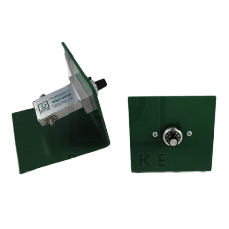
Bracke BM Series continuously variable 50-ohm RF attenuators with SMA connectors, frequency ranges from 1 to 18 GHz and attenuation up to 40 dB.
Bracke Manufacturing continuously variable RF attenuators provide manual and continuous adjustment of signal attenuation in 50-ohm coaxial systems. The product family includes models covering frequency ranges between 1 GHz and 18 GHz, with maximum attenuation ranges of up to 40 dB.
The units feature SMA female connectors and are designed for integration into laboratory setups, RF test systems and customised test benches. A mechanical scale supports repeatable adjustment of the required attenuation value.
Advantages
- Continuously variable attenuation for flexible RF test and measurement tasks
- Model-dependent attenuation ranges of 0 to 7 dB, 0 to 30 dB or 0 to 40 dB
- Frequency coverage across the available models from 1 to 18 GHz
- 50-ohm impedance for use in standard coaxial RF systems
- Robust construction using passivated stainless steel and an aluminium mounting plate
- Gold-plated contacts and PTFE insulators
- Mechanical control with a clearly graduated scale
- Model selection and system integration support from EMCO RF and microwave specialists
Key features
- Function: continuously variable coaxial attenuator
- Impedance: 50 ohms
- Connectors: SMA female
- Frequency ranges: depending on the model, 1 to 2 GHz, 4 to 8 GHz, 8 to 12.4 GHz, 12 to 18 GHz or 12.4 to 18 GHz
- Attenuation range: up to 7 dB, 30 dB or 40 dB depending on the model
- Average power: 5 W or 7 W depending on the model
- Peak power: up to 3 kW for the specified models
- Insertion loss: 0.5 dB or 0.75 dB maximum depending on the model
- VSWR: between 1.50:1 and 2.0:1 maximum depending on the model
- Housing material: passivated stainless steel
- Mounting plate: aluminium
- Contacts: gold plated
- Insulators: PTFE
Typical applications
- Adjustment of defined RF signal levels in laboratory and production test systems
- Characterisation of RF and microwave components
- Calibration and verification setups
- Receiver sensitivity and dynamic range measurements
- Signal-level matching between RF generators, amplifiers, receivers and measuring instruments
- Development and testing of communication, radar and microwave systems
- Integration into customised automatic or manual test systems
Additional information
Selection of the appropriate attenuator primarily depends on the frequency range, required attenuation range, permissible VSWR, insertion loss and power-handling capability. As the individual versions have different electrical and thermal limits, these parameters must be considered during system design.
Available models
The Rotary Attenuators are available in several configurations with BNC, SMA, N and F connectors, different frequency ranges and attenuation step sizes. For easier product selection, the references are grouped by connector family.
BNC Female Rotary Attenuators – 50 Ω and 75 Ω
| Reference | Impedance | Frequency range | Attenuation range | Step size | Configuration |
|---|---|---|---|---|---|
| BM10030 | 50 Ω | Up to 1 GHz | 0 to 1 dB | 0.1 dB | Bench mount, single stage |
| BM10031 | 50 Ω | Up to 1 GHz | 0 to 100 dB | 10 dB | Bench mount, single stage |
| BM10032 | 50 Ω | Up to 2 GHz | 0 to 10 dB | 1 dB | Bench mount, single stage |
| BM10033 | 50 Ω | Up to 2 GHz | 0 to 70 dB | 10 dB | Bench mount, single stage |
| BM10034 | 50 Ω | Up to 2 GHz | 0 to 100 dB | 10 dB | Bench mount, single stage |
| BM10035 | 50 Ω | Up to 2 GHz | 0 to 1 dB | 0.1 dB | Bench mount, single stage |
| BM10023 | 50 Ω | Up to 2 GHz | 0 to 80 dB | 1 dB | Bench mount, double stage |
| BM10022 | 50 Ω | Up to 2 GHz | 0 to 110 dB | 1 dB | Bench mount, double stage |
| BM10024 | 50 Ω | Up to 2 GHz | 0 to 81 dB | 0.1 dB | Bench mount, triple stage |
| BM10025 | 75 Ω | Up to 500 MHz | 0 to 1 dB | 0.1 dB | Bench mount, single stage |
| BM10026 | 75 Ω | Up to 500 MHz | 0 to 10 dB | 1 dB | Bench mount, single stage |
| BM10027 | 75 Ω | Up to 500 MHz | 0 to 70 dB | 10 dB | Bench mount, single stage |
| BM10029 | 75 Ω | Up to 1 GHz | 0 to 1 dB | 0.1 dB | Bench mount, single stage |
| BM10028 | 75 Ω | Up to 1 GHz | 0 to 10 dB | 1 dB | Bench mount, single stage |
SMA Female Rotary Attenuators – 50 Ω
| Reference | Frequency range | Attenuation range | Step size | Configuration |
|---|---|---|---|---|
| BM10092 | DC to 1 GHz | 0 to 100 dB | 10 dB | Bench mount, single stage |
| BM10087 | DC to 2 GHz | 0 to 30 dB | 1 dB | Bench mount, single stage |
| BM10094 | DC to 2.5 GHz | 0 to 100 dB | 10 dB | Bench mount, single stage |
| BM10054 | Up to 2.5 GHz | 0 to 50 dB | 1 dB | Bench mount, single stage |
| BM10091 | DC to 3 GHz | 0 to 10 dB | 1 dB | Bench mount, single stage |
| BM10070 | Up to 6 GHz | 0 to 1 dB | 0.1 dB | Bench mount, single stage |
| BM10071 | Up to 6 GHz | 0 to 10 dB | 1 dB | Bench mount, single stage |
| BM10072 | Up to 6 GHz | 0 to 60 dB | 10 dB | Bench mount, single stage |
| BM10073 | Up to 18 GHz | 0 to 9 dB | 1 dB | Bench mount, single stage |
| BM10074 | Up to 18 GHz | 0 to 69 dB | 1 dB | Bench mount, single stage |
| BM10075 | Up to 18 GHz | 0 to 80 dB | 10 dB | Bench mount, single stage |
| BM10076 | Up to 18 GHz | 0 to 99 dB | 1 dB | Bench mount, single stage |
N Female Rotary Attenuators – 50 Ω
| Reference | Frequency range | Attenuation range | Step size | Configuration |
|---|---|---|---|---|
| BM10097 | Up to 2 GHz | 0 to 70 dB | 1 dB | Bench mount, single stage |
| BM10093 | DC to 2.5 GHz | 0 to 50 dB | 1 dB | Bench mount, single stage |
| BM10077 | Up to 6 GHz | 0 to 1 dB | 0.1 dB | Bench mount, single stage |
| BM10078 | Up to 6 GHz | 0 to 10 dB | 1 dB | Bench mount, single stage |
| BM10079 | Up to 6 GHz | 0 to 60 dB | 10 dB | Bench mount, single stage |
F Female Rotary Attenuators – 75 Ω
| Reference | Frequency range | Attenuation range | Step size | Configuration |
|---|---|---|---|---|
| BM10096 | DC to 1 GHz | 0 to 10 dB | 1 dB | Bench mount, single stage |

Related articles
 BRACKE Manufacturing now at EMCO: RF and Microwave Components