


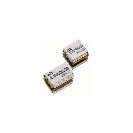

Ceramic triplexer – three frequency bands, custom design, 0.600 to 3.000 GHz | JQL Electronics / Dorado

JQL ceramic triplexers for three RF frequency bands. Multiple JRTP band configurations plus custom designs based on frequency band, insertion loss, rejection and isolation, available through EMCO.
The JQL Technologies ceramic triplexers are passive RF components designed for frequency-selective routing or combining of three defined frequency bands. The product family includes several JRTP configurations covering different combinations of RF bands.
The models currently listed by JQL use frequency bands between 0.698 and 2.170 GHz. JQL also provides custom design based on technical requirements including frequency band, insertion loss, rejection and isolation.
Advantages
- Three frequency bands in one component: triplexer architecture for frequency-selective processing of three separate RF bands.
- Multiple band combinations: several JRTP models are available for different frequency configurations.
- Custom design: configurations can be adapted according to frequency band, insertion loss, rejection and isolation requirements.
- Technical selection support from EMCO: assistance in selecting an appropriate configuration for the required RF or microwave application.
Key features
- Component type: ceramic triplexer
- Number of frequency bands: three
- Product category frequency range: 0.600 to 3.000 GHz
- Frequency range covered by currently listed band configurations: 0.698 to 2.170 GHz
- Available selection parameters: Band 1, Band 2, Band 3, insertion loss, rejection and return loss
- Custom design parameters: type, frequency band, insertion loss, rejection and isolation
Typical applications
- DAS – Distributed Antenna Systems
- Public safety radio systems
- Radar
- Radio links
- SatCom
- Wireless communication systems
Additional information
JQL offers several triplexer configurations within its ceramic filter family as well as custom solutions. EMCO provides technical support for selecting a suitable component according to the required frequency bands and insertion loss, rejection and isolation requirements.
Model comparison
| Model | Band 1 (GHz) | Band 2 (GHz) | Band 3 (GHz) | Insertion Loss* | Rejection* | Return Loss* |
|---|---|---|---|---|---|---|
| JRTP8F742L8J744FC | 0.698–0.716 | 0.728–0.757 | 0.776–0.787 | 3.5 | 45 | 17 |
| JRTP8J1848F4D897FA | 0.880–0.915 | 1.710–1.785 | 1.920–1.980 | 3 | 50 | 15 |
| JRTP8J919R4D2017A | 0.885–0.909 | 0.930–0.954 | 2.010–2.025 | 3 | 50 | 18 |
| JRTP12Q1920F4D922A | 0.885–0.960 | 1.710–1.880 | 1.920–2.170 | 3 | 40 | 15 |
| JRTP6J921F4D1900A | 0.889–0.909 | 0.934–0.954 | 1.880–1.920 | 2.7 | 45 | 18 |
| JRTP925LF8J1920FB | 0.890–0.960 | 1.710–1.880 | 1.920–2.170 | 2.2 | 50 | 10 |
| JRTP12Q1920F4D922A | 0.925–0.960 | 1.805–1.880 | 2.110–2.170 | 3 | 50 | 15 |
| JRTP8J1770R4D2017A | 1.710–1.735 | 1.805–1.830 | 2.010–2.025 | 3 | 50 | 18 |

Related articles
 BRACKE Manufacturing now at EMCO: RF and Microwave Components