


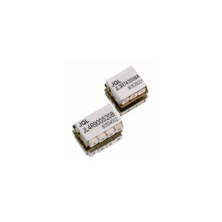

Ceramic Duplexers/Diplexers – TX/RX band combinations from 820 MHz to 2.69 GHz | JQL Electronics / Dorado

Compact JQL ceramic duplexers and diplexers for frequency-selective separation of TX and RX signal paths, with multiple band combinations and custom-design capabilities.
JQL Technologies ceramic duplexers and diplexers are passive frequency-selective components designed to separate different TX and RX frequency ranges within a common RF system.
The documented portfolio includes numerous band combinations ranging from approximately 820 MHz to 2.69 GHz. Individual references differ primarily in terms of TX band, RX band, insertion loss, rejection and return loss.
Ceramic filter technology combines the two frequency-selective signal paths within a common component. For requirements outside the standard references, JQL also provides custom-design capabilities based on defined filter parameters.
Advantages
- Multiple TX/RX frequency combinations for different RF and wireless systems
- Frequency-selective separation of two signal paths in a ceramic filter solution
- Insertion loss from 1.0 dB on appropriately specified models
- Rejection up to 65 dB within the documented standard references
- Return loss up to 20 dB on selected models
- Documented operating temperature range of −40 to +85 °C
- Custom design for application-specific frequency and filter requirements
- Technical support from EMCO for selection and specification matching
Key features
- Product type: Ceramic Duplexer / Diplexer
- Documented frequency coverage: approximately 0.820 to 2.690 GHz, depending on reference
- Insertion loss: 1.0 to 4.0 dB across the documented models
- Rejection: 35 to 65 dB across the documented models
- Return loss: 10 to 20 dB, depending on reference
- Operating temperature: −40 to +85 °C
- Custom-design parameters: type, frequency band, insertion loss, rejection and isolation
Typical applications
- DAS – Distributed Antenna Systems
- Public Safety
- Radar
- Radio Link
- SatCom
- Wireless
- TX/RX frequency separation in RF communications systems
- Integration into compact frequency-selective RF assemblies
Additional information
Selection of the appropriate ceramic duplexer or diplexer primarily depends on the required TX and RX frequency ranges, acceptable insertion loss, required rejection and return loss.
JQL also lists a power value for the available models. As the product overview does not state an unambiguous unit for this value, it has deliberately not been reproduced here as a technical power specification.
For requirements not covered by a standard reference, JQL provides custom design. The manufacturer identifies type, frequency band, insertion loss, rejection and isolation as key design parameters.
EMCO Elektronik supports the technical selection of suitable JQL ceramic duplexers and diplexers and the matching of TX/RX band combinations and filter parameters to the relevant RF and system application.
| Reference | TX | RX | Insertion Loss | Rejection | Return Loss | Temperature |
|---|---|---|---|---|---|---|
| JRP827F872N10N15FC | 0.820–0.835 GHz | 0.865–0.880 GHz | 2.0 dB | 65 dB | 16 dB | −40 to +85 °C |
| JRP827F872R10N15FA | 0.820–0.835 GHz | 0.865–0.880 GHz | 1.8 dB | 60 dB | 18 dB | −40 to +85 °C |
| JRP827F872F10N15FA | 0.820–0.835 GHz | 0.865–0.880 GHz | 3.0 dB | 45 dB | 18 dB | −40 to +85 °C |
| JRP836F881F10N25FE | 0.824–0.849 GHz | 0.869–0.894 GHz | 3.8 dB | 50 dB | 13 dB | −40 to +85 °C |
| JRP836R881N10N25FJ | 0.824–0.849 GHz | 0.869–0.894 GHz | 3.0 dB | 55 dB | 14 dB | −40 to +85 °C |
| JRP830F875N10N10FU | 0.825–0.835 GHz | 0.870–0.880 GHz | 2.0 dB | 55 dB | 18 dB | −40 to +85 °C |
| JRP837R882P12N15FA | 0.830–0.845 GHz | 0.875–0.890 GHz | 2.2 dB | 55 dB | 18 dB | −40 to +85 °C |
| JRP897F942F10N24FH | 0.885–0.909 GHz | 0.930–0.954 GHz | 3.5 dB | 40 dB | 16 dB | −40 to +85 °C |
| JRP897F942N10N24FO | 0.885–0.909 GHz | 0.930–0.954 GHz | 3.5 dB | 50 dB | 14 dB | −40 to +85 °C |
| JRP897F942R10N24FE | 0.885–0.909 GHz | 0.930–0.954 GHz | 2.0 dB | 55 dB | 18 dB | −40 to +85 °C |
| JRP900F945N10N30FE | 0.885–0.915 GHz | 0.930–0.960 GHz | 2.2 dB | 47 dB | 20 dB | −40 to +85 °C |
| JRP902F947R10N25FC | 0.890–0.915 GHz | 0.935–0.960 GHz | 2.0 dB | 58 dB | 18 dB | −40 to +85 °C |
| JRP912F957N10N06FS | 0.909–0.915 GHz | 0.954–0.960 GHz | 1.8 dB | 60 dB | 18 dB | −40 to +85 °C |
| JRC1539R1650N10N42-49FG | 1.518–1.560 GHz | 1.626–1.675 GHz | 1.1 dB | 56 dB | 16 dB | −40 to +85 °C |
| JRP1547R1651N10N59-50TC | 1.518–1.559 GHz | 1.626–1.676 GHz | 2.0 dB | 60 dB | 14 dB | −40 to +85 °C |
| JRC1732F2132F10N45FB | 1.710–1.755 GHz | 2.110–2.155 GHz | 2.0 dB | 50 dB | 18 dB | −40 to +85 °C |
| JRP1747F1842F10N75FG | 1.710–1.785 GHz | 1.805–1.880 GHz | 4.0 dB | 35 dB | 13 dB | −40 to +85 °C |
| JRP1747F1842R10N75FD | 1.710–1.785 GHz | 1.805–1.880 GHz | 3.5 dB | 55 dB | 15 dB | −40 to +85 °C |
| JRP1880F1960N10N60FI | 1.850–1.910 GHz | 1.930–1.990 GHz | 3.5 dB | 50 dB | 10 dB | −40 to +85 °C |
| JRC1950F2140F10N60FN | 1.920–1.980 GHz | 2.110–2.170 GHz | 1.5 dB | 50 dB | 18 dB | −40 to +85 °C |
| JRP1950F2140R10N60FE | 1.920–1.980 GHz | 2.110–2.170 GHz | 1.0 dB | 60 dB | 18 dB | −40 to +85 °C |
| JRP1947F2137F10N15FC | 1.940–1.955 GHz | 2.130–2.145 GHz | 1.8 dB | 60 dB | 18 dB | −40 to +85 °C |
| JRP2535F2655N10N70FD | 2.500–2.570 GHz | 2.620–2.690 GHz | 3.0 dB | 50 dB | 14 dB | −40 to +85 °C |
| JRP2535R2655F10N70FE | 2.500–2.570 GHz | 2.620–2.690 GHz | 4.0 dB | 50 dB | 15 dB | −40 to +85 °C |

Related articles
 BRACKE Manufacturing now at EMCO: RF and Microwave Components