


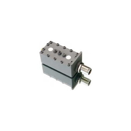

Cavity bandpass filters – broad frequency selection and custom design | JQL Electronics / Dorado

JQL cavity bandpass filters for RF, microwave and mmWave applications. Broad frequency selection, multiple interfaces and custom filter design available.
JQL Technologies cavity bandpass filters are designed to transmit defined RF and microwave frequency ranges while suppressing unwanted signals outside the required passband. The portfolio includes a broad selection of standard configurations for applications ranging from VHF/UHF frequencies to microwave and mmWave systems.
Available models differ in terms of passband, insertion loss, rejection, return loss, operating temperature and RF interface. Depending on the reference, configurations include SMA, N, 7/16, Mini-UHF, K/2.4 mm, drop-in and PIN interfaces.
In addition to catalogued products, JQL supports custom bandpass filter designs. Manufacturer-defined design parameters include frequency band, insertion loss, rejection and isolation.
Advantages
- Broad frequency coverage from VHF/UHF through microwave and mmWave frequencies
- Wide selection of passband widths and filter characteristics
- Low-insertion-loss models available for loss-sensitive RF signal paths
- High out-of-band rejection on appropriately specified models
- Multiple RF interfaces and integration formats for different system architectures
- Custom design according to application-specific filter parameters
- Configurations available for different temperature and power requirements
- Technical support from EMCO for product selection and specification matching
Key features
- Filter type: Cavity bandpass filter
- Frequency ranges: numerous models from VHF/UHF frequencies to above 40 GHz
- Selection parameters: passband, insertion loss, rejection, return loss, power, temperature and connector
- Custom-design parameters: type, frequency band, insertion loss, rejection and isolation
- Interface options: depending on model, including SMA, N, 7/16, Mini-UHF, K/2.4 mm, drop-in and PIN configurations
Typical applications
- DAS – Distributed Antenna Systems
- Public safety radio systems
- Radar systems
- Radio links
- SatCom
- Wireless communication systems
- RF and microwave signal conditioning
- Frequency-selective assemblies and subsystems
- Laboratory, test-bench and system integration
Additional information
The electrical specifications vary significantly between individual JQL references. Passband, insertion loss, rejection, return loss, power, temperature range and connector therefore need to be matched to the specific application.
For requirements that cannot be covered by a standard model, JQL provides custom-design capabilities based on the required filter type and electrical target parameters. Frequency band, insertion loss, rejection and isolation can be defined as key design criteria.
EMCO Elektronik supports the selection of the appropriate JQL bandpass filter and the technical matching of the filter characteristics to the application. This includes evaluating the required passband, out-of-band rejection, insertion loss, RF interface and mechanical or system-level integration requirements.
Model overview:
| Reference | Passband | Insertion Loss | Return Loss | Temperature | Connector |
|---|---|---|---|---|---|
| JFLC0092T0108SF | 0.0925–0.1025 GHz | 2 dB | 14 dB | −20 to +65 °C | SMA Female |
| JFCB0210T0240NF | 0.210–0.240 GHz | 0.8 dB | 17.7 dB | −10 to +70 °C | N Female |
| JFCB0380T0470DF | 0.380–0.470 GHz | 1.5 dB max., 1.3 dB typ. | 14 dB | −20 to +60 °C | 7/16 Female |
| JFCB0762T0860UF | 0.762–0.8605 GHz | 1.0 dB | 18 dB | −30 to +60 °C | Mini-UHF |
| JFCB0960T1215SF | 0.960–1.215 GHz | 1.8 dB | 10.9 dB | −20 to +55 °C | SMA |
| JFCB1000T1700SF | 1.0–1.7 GHz | 0.5 dB | 15.6 dB | −50 to +55 °C | SMA Female |
| JFCB2025T2120NF-C | 2.025–2.120 GHz | 0.5 dB | 15.6 dB | −50 to +55 °C | N Female |
| JFCB2200T2400SF-A | 2.200–2.400 GHz | 0.5 dB | 16 dB | −10 to +50 °C | SMA |
| JFCB2700T2900SF | 2.700–2.900 GHz | 1.5 dB | 14 dB | 0 to +85 °C | SMA Female |
| JFCB3300T3400SF | 3.300–3.400 GHz | 0.5 dB | 17.7 dB | −40 to +85 °C | SMA |
| JFCB3400T3600SF | 3.400–3.600 GHz | 0.5 dB | 17.7 dB | −40 to +85 °C | SMA |
| JFCB4400T5000SF | 4.40–5.00 GHz | 0.7 dB | 14 dB | −40 to +85 °C | SMA Female |
| JFCB5000T5850SF | 5.0–5.85 GHz | 0.7 dB | 14 dB | −40 to +85 °C | SMA Female |
| JFCB7600T8500SF | 7.6–8.5 GHz | 0.4 dB | 15.6 dB | −50 to +55 °C | SMA |
| JFCB10K8T11K0SF | 10.8–11.0 GHz | 2.0 dB | 15.6 dB | −20 to +55 °C | SMA |
| JFCB11K2T11K4SF | 11.2–11.4 GHz | 2.0 dB | 15.6 dB | −20 to +55 °C | SMA |
| JFCB14K0T15K3SF | 14.0–15.3 GHz | 3.5 dB | 16 dB | −20 to +65 °C | SMA |
| JFCB17K0T18K3SF | 17.0–18.3 GHz | 3.5 dB | 16 dB | −20 to +65 °C | SMA |
| JFCB21K5T22K8SF | 21.5–22.8 GHz | 3.5 dB | 16 dB | −20 to +65 °C | SMA Female |
| JFCB23K0T24K3SF | 23.0–24.3 GHz | 3.5 dB | 16 dB | −20 to +65 °C | SMA Female |
| JFCB36K5T38K0KF | 36.5–38.0 GHz | 1.0 dB | 16 dB | +10 to +35 °C | K Female |
| JFCB37K5T42K6KF | 37.45–42.25 GHz | 1.5 dB | 18 dB | −30 to +70 °C | 2.4 mm Female / 2.4 mm Male |

Related articles
 BRACKE Manufacturing now at EMCO: RF and Microwave Components